IOT FISHTANK (PART 1) – Chris Fraser (Senior Developer Technology Incubation) Derivco Durban
I have a very average fish tank. I inherited it about 10 years ago from some friends moving abroad. It has survived many moves with me and I have become quite attached to my fish-friends. On a good day, it looks like this.

The problem we are solving today is that it often looks like this.

I am very bad at remembering to turn the lights on. Also, if the lights are left on for too long during a 24hr period, algae tends to grow. Optimally, I would like the lights on when I am home and to vary the time on from 8 to 12 hours a day.
Currently I have Beamswork LED-200 lights installed. These run off a 12V power supply and have an annoying switch on the unit that I must open the fish tank lid to operate. I am also a little worried about moisture getting into the enclosure as it is not very well sealed.

Taking all these things into account, I have come up with the following requirements which I will explain in detail later.
Requirements:
- Secure IOT solution
- Single energy efficient power supply (No batteries)
- Safe (Death proof)
- Easy to swap lights in future
- Cheap
Secure IOT solution
For the first phase of this project I will only allow control of the device within my local Wi-Fi network. In Part 2 we will be exploring connectivity to the outside world. For now, being on my private Wi-Fi with no external connectivity is enough security for me.
Single Power Supply
My tank lights require a 12V power supply and draw a lot less than 2A on bright. They came with a wallwart style power supply with a stupid US plug. This is no good for hacking as it is a sealed unit. Fortunately, I have many different 12V switching supplies for LEDs.

This one has sufficient power and is nice and compact. These switching power supplies are also very efficient.
Most LED lighting runs off 12V so this also ticks the “easy-to-swap-lights-in-future” box.
One important thing to check with these power supplies is the output voltage. Quality seems to be improving in these devices out of China, but it doesn’t hurt to check.

Safe (Death proof)
This project deals with mains voltage which is 220V in South Africa. Mains voltage can kill you. At a minimum, it will cause severe electrical burns. To keep things safe, I want all the 220V electronics in an enclosure.
Cheap
As much as I love my fish, I would like to remain frugal in ensuring their happiness. To this end, I plan on using a microprocessor for the job. Something like a Raspberry Pi would work well but would be overkill. My goto microprocessor of late is the ESP8266made by Espressif. It is cheap and includes a robust Wi-Fi stack. To top it off, you can program it with the Arduino IDE. This makes progamming quick and speeds up prototyping.
I initially planned on using an NodeMCU and relay for this project, but then I remembered these Sonoff modules that arrived from Bangood recently.

These combine the an ESP8266 IC (as its brain), relay and a power supply. This makes them perfect as they have everything I need. The only issue is that they come with a terrible Chinese firmware and iOS/Android App.

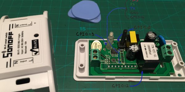
Before it would let me do anything, it wanted my cellphone number. This is where I draw the line. So, I took out my trusty spudger and tore it to pieces. With a little bit of digging I found the pinout.

WARNING: This device uses 220V electrical supply and can kill you. Be very careful. If you don’t know what you are doing, do not try this at home! Never connect to 220V while the board is exposed.
Fortunately, we have all the pins available to replace the Chinese firmware on the ESP8266 with our own.
To do this, we are going to need a USB to TTL converter. I used one of these, but there are many variants out there. The important thing is that the logic level is 3.3V and it can supply the ESP about 200mA of 3.3V power. This USB to TTL converter can only supply 26mA according to the datasheet, so I used a separate power supply. Having too little power will mess with the Wi-Fi and cause instability. If you are in a pinch, two alkaline batteries supply more than enough.

To get the dev environment up and running look at ESP8266 core for Arduino.
There are many boilerplate samples on GitHub. I chose to fork ImUrlaub/Sonoff as it is the simplest. You can grab the code I used here.
The programming procedure is simple. Connect GND to GND, RX to TX and TX to RX. Before connecting the 3.3V power source, hold down the button on the Sonoff device then power it on. This will put the device into flashing mode so you can upload to it.
For now, the interface is simple. The device connects to a given Wi-Fi AP. There is a basic web page that allows me to switch the light on and off if I am on the same network. MDNS has been implemented so I can browse to this by going to http://fishtank.local. The button on the Sonoff also toggles the on/off state.
Putting it all together
After some initial testing, I designed an enclosure for everything and 3D printed it. I broke out the programming pins to a header on the box so I could program it externally. If the Sonoff is powered externally, you must not connect the 3.3V power when programming. I decided to put a hard override switch in that bridges the 220V live wire in case I wanted to override the Sonoff.


There was one major problem with V1. The ESP8266 on the underside of the Sonoff board produces quite a lot of heat when connecting to Wi-Fi. Insulating it with foam between the power supply and board caused it to overheat.
The beauty of 3D printing is that you can rapidly iterate on ideas. For V2, I designed a bracket to hold the Sonoff board some distance from the power supply. This created a nice air gap to dissipate heat. I also had to replace the Sonoff button with an external button because I broke it. 🙁


The design files for this project are up on Thingiverse.
So far, my fish seem very happy with their new (over-engineered) sun. Stay tuned for Part 2 where we connect to the external interweb and implement a timer switch.